
Adapted from a paper by Jean-Pierre Courjaud – F6DZP
Gaston Bertels – ON4WF
IQ Symbols and Constellations
A DVB-S transmitter produces a continuous Transport Stream of data (see Introduction to digital satellite television technology). The Transport Stream modulates the RF carrier. In general, DATV uses QPSK modulation.
The data transmitted are IQ Symbols or “Symbols” for short. IQ refers to the “In phase” and “Quadrature” axes of a polar diagram.

The symbols can be considered as (I,Q) coordinates of a point on the polar diagram. If we assign each quadrant of the polar diagram a binary value of 00, 01, 10 and 11, each symbol represents a 2 bit number. Four symbols represent an 8 bit number, the classical byte. Thus, from the Transport Stream we can extract the bytes of the encoded DVB signal.
When the IQ points are located in the centres of the quadrants, the symbols can be read easily. But transmit and receive shortcomings, as well as poor conditions, can cause dispersion of the IQ points and result in reading errors. Efficient error correction techniques will considerably help recover the data.
The polar representation of the IQ points is referred to as “constellations”. Constellations are excellent indicators of the quality of the received signal. The more the points are concentrated in the centre of each quadrant, the better the reception.
Measuring the signal
The schematic diagram at the end of the Introduction to digital satellite television technology is similar to a Russian Matryoshka doll with several layers of information. At each level of information, measurements are possible. The reference for these measurements is the ETSI document ETR290 Measurement guidelines for DVB systems, available at http://www.etsi.org/deliver/etsi_etr/200_299/290/01_60/etr_290e01p.pdf. ETSI is the European Telecommunications Standards Institute.
Measurements can be done:
- on RF (signal strength and CNR)
- on Symbol data (MER, VBER, CBER)
- on the Transport Stream (PCR)
- on MPEG decoding.
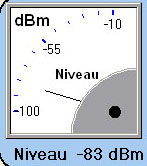
RF level
This is the traditional measurement of the HF signal, usually visualized by a vu-meter in dBm.
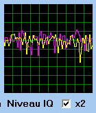
IQ level
The Zero Tuner delivers IQ signals with an amplitude of 0 to 1Vpp (some chips deliver 0 to 2Vpp). The frequency is a few megahertz. These signals are measurable with an oscilloscope or a spectrum analyser when available in analog format. But it is easier to visualize them once they are digitalized (at about 100MHz on 6 or 8 bits, depending the QPSK demodulator).
The small Tutioune oscilloscope shows the levels of these signals.
CNR (or C/N)
The Carrier-to-Noise Ratio is not always significant for DVB. Of course, to demodulate a digital stream becomes increasingly difficult as signals are buried deeper in the noise. But, on the other hand, a high CNR level, say 30 dB, does not mean, that decoding will be easy. Indeed, a high CNR does not provide any information on possible degradation of the DVB modulation.
Analog SNR (on analog IQ as extracted from RF)
This is the ratio between the signal of interest and noise. The signal we are interested in is called Baseband and corresponds to phase modulated I and Q signals. The frequency depends of the Symbol Rate, which is the number of Symbols per second.
Analog SNR is measured the same way as CNR, but on IQ signals. Signal amplitude is 0 to 1 (or 2) Vpp at a frequency of few megahertz. At the entry of the QPSK demodulator, the SNR shall be at least 1 dB in order to obtain synchronization.
Digital SNR (on digitalized IQ)
I and Q are now digitized at about 100 MHz on 6 or 8 bits. Each IQ Symbol can take one of four values: 00, 01, 10 and 11. This represents a dynamic range (DR) of 4, which is 6.02 dB.
The global dynamic range of a system depends on the number of bits used for encoding. For example, audio CD’s are encoded on 16 bits. Therefore it is said, that a CD has a theoretical dynamic range of 6.02 x 16 = 96 dB.
When I Q Symbols are encoded on 8 bits, their theoretical dynamic range is 6.02 x 8 = 48 dB. But, in practice, the Effective Number of Bits (ENOB) will be lower, say 7.5. ENOB cab be considered as a computing coefficient. With ENOB at 7.5, the actual dynamic range of the IQ signal is 6.02 x 7.5 = 45 dB.
Measuring Modulation Errors
Without transmission errors, traces of IQ Symbols appear at well defined places indicated as blue dots in this diagram.
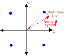
There are two methods to measure modulation errors:
- Error Vector Magnitude (EVM), measures distorsion elements (Magnitude and Phase), expressed as a percentage (%) of the maximum voltage in the constellation at sampling times
- Modulation Error Ratio (MER), measures the same distorsion elements, but computed as an average over a number of IQ Symbols.
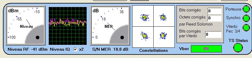
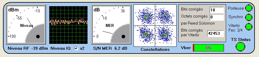
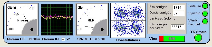
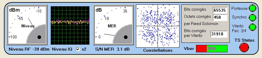
In these four Tutioune screenshots one can see the correlation between MER and Constellations. ¨Please note, that the four measurements where taken at quasi contant RF level. When MER dropped under 3.6.dB, the Transport Stream collapsed.
ETSI ETR290 states:
MER is the preferred measurement for the following reasons:
- The sensitivity of the measurement, the typical magnitude of measured values, and the units of measurement combine to give MER an immediate familiarity for those who have previous experience of C/N or SNR measurement.
- MER can be regarded as a form of Signal-to-Noise ratio measurement that will give an accurate indication of a receiver’s ability to demodulate the signal, because it includes, not just Gaussian noise, but all other uncorrectable impairments of the received constellation as well.
- If the only significant impairment present in the signal is Gaussian noise then MER and SNR are equivalent
Forward Error Correction (FEC)
In the transmitter, Forward Error Correction is initiated by adding redundancy to the transmitted information, using an algorithm. The HamVideo transmitter uses FEC ½.
In the receiver, FEC processing is an integral part of the analog-to-digital conversion.The Viterbi decoder implements an algorithm to demodulate digital data from the analog signal, corrupted by noise.
The Bit Error Rate (BER) is measured pre and post Viterbi and noted respectively CBER and VBER.
Reed Solomon error correction is applied at byte level.